Coordinates
The Info panel in DS9 dynamically displays the coordinate values corresponding to the current mouse position in the image, physcial and WCS coordinate system. WCS ('World coordinate system') is a generic name for coordinates defined in the FITS file header as a parameterized mapping from the image physical coordinates.
DS9 supports two kinds of coordinates: (1) WCS coordinates, which are (usually) nonlinear mappings of the pixel plane to the celestial (or other) sphere, and (2) linear rotation/translation mappings which usually represent instrumental coordinates of some kind.
The WCS systems include a primary WCS, and optionally secondary WCS systems labelled WCS A to WCS Z.
The linear systems have four subtypes: Image, physical, amplifier and detector. The image system is the pixel number system of the (possibly) rebinned image being displayed by DS9. The physical system is a linear transformation between the current image coordinates and an 'original' detector coordinate system. Amplifier and Detector coordinates are piecewise linear mappings defined to support mosaic detectors and describe how the chips are arranged relative to one another.
Image, physical and WCS
The underlying 2D image has pixel numbers than run from 1 to NX, 1 to NY along each axis. Image pixel coordates of pixel 1,1 run from 0.5 to 1.5, with (1.0, 1.0) in the center of the pixel. The physical coordinates represent the rebinned image (for example when created from an event file, see later). If an image is rebinned by a factor m around a reference point with image coordinates X0, Y0 and physical coordinates x0, y0, then the corresponding physical coordinates for an arbitary location X,Y are
(x,y) = (x0 + (X-X0) / m, y0 + (Y-Y0) / m )
The WCS coordinates usually involve a nonlinear transformation applied to the physical coordinates P = (x,y) using the reference physical position P0 = (x0,y0) (CRPIX keyword family), the corresponding world coordinate position W0 = (xw0, yw0 ) (CRVAL keyword family), the scale factors δ = (δX, δY) (CD keyword family or the older CDELT) and the transformation function T (CTYPE keyword family).
W = T(P,P_0,W_0,δ)
The FITS header will usually define a single coordinate system, typically equatorial coordinates RA and Dec. However DS9 can automatically perform transformations between certain standard astronomical coordinate systems. The user can, for example, select WCS - Galactic. In this case the code reads image coordinates from the cursor position, applies the physical transform using header keywords to get physical coordinates, then applies the (RA,Dec) transform from the header keywords to map physical to (RA, Dec), and finally maps (RA, Dec) to galactic (l,b) using standard formulae.
| Command: | wcs sky fk4|fk5|icrs|galactic|ecliptic |
| Menu: | WCS - FK4/FK5/ICRS/Galactic/Ecliptic |
| Description: | Set celestial coordinate system displayed in info paneto Equatorial FK4, Equatorial FK5, Equatorial ICRS, Galactic (lII,bII), or Ecliptic. |
FITS coordinate keywords
The standard FITS keywords for FITS images, in use since 1979, are:
| CRPIXn | Pixel number coordinate at reference point for axis n |
| CRVALn | World cordinate value at reference point for axis n |
| CDELTn | Pixel size, degrees per pixel at reference point along axis n, now deprecated |
| CDn_m | Modern replacement for CDELT, matrix including skew for axis n,m |
For binary tables, similar keywords are used for defining coordinates on table column n:
| TCRPXn | Pixel number coordinate at reference point for column n |
| TCRVLn | World cordinate value at reference point for column n |
| TCDLTn | Pixel size, degrees per pixel at reference point along column n |
| TCDn_m | Alternative to TCDLT, matrix including skew for axis n,m |
The CRPIX, TCRPX sets of keywords define the primary WCS (world coordinate system).
We can also define additional WCS systems on the same data (for example, J2000 and B1950 and Galactic), by appending a letter A to Z to the standard keywords. We can attach a name to the WCS with the WCSNAME keyword. For example, we can define a WCS P with
| CRPIXnP | Pixel number coordinate at reference point for column n |
| CRVALnP | World cordinate value at reference point for column n |
| CDELTnP | Pixel size, degrees per pixel at reference point along column n |
| WCSNAMEP = "value" | Name for WCS system |
DS9 treats "WCSNAMEP = 'PHYSICAL'" as special, defining the 'Physical' coordinate system.
In addition to the keywords above from the FITS standard, DS9 also recognizes keywords used by the IRAF system defining a linear 2D transformation with M (n x n rotation matrix) and V (n x 1 translation vector) values:
| Keyword | DS9 coordinate system |
| LTMx_x/LTVx | Physical |
| DTMx_x/DTVx | Detector |
| ATMx_x/ATVx | Amplifier |
If a WCSNAMEP= PHYSICAL system is present, it supersedes any LTM/LTV keywords.
| Command: | wcs system wcs|wcsa...wcsz |
| Menu: | WCS - WCS/Multiple WCS |
| Description: | Select which WCS system to display in the info panel |
| Command: | wcs reset |
| Menu: | - |
| Description: | Resets WCS to default system? |
Coordinate format control
| Command: | wcs skyformat degrees|sexagesimal |
| Menu: | WCS - Degrees/Sexagesimal |
| Description: | allows user to control which format the coordinates are displayed in. |
| Command: | prefs precision n1 n2 n3 n4 n5 n6 n7 n8 n9 |
| Menu: | Edit - Preferences - Precision |
| Description: | Edit - Preferences - Precision - Coordinates allows users to control the precision used for coordinates (in the info panel and inother display contexts). The precision value used is the number of digits to be displayed after the decimal point.Different precision settings are provided for coordinates of linear type ( n1, default 8), those in decimal degrees ( n2, default 7), in hours-min-sec format( n3, default 4), and in deg-min-sec format ( n4, default 3).Edit - Preferences - Precision - Length allows users to control the precision used for display of length measurements.The precision value used is the number of digits to be displayed after the decimal point.Different precision settings are provided for coordinate lengths of linear type ( n5, default 8), those in decimal degrees ( n6, default 7), in arcmin ( n7, default 5)and in arcsec ( n8, default 3).Edit - Preferenc |
Support for multiple WCS systems
Most FITS data will have a single WCS but the standard supports the file having multiple 'alternate WCS' definitions, each labelled with a suffix letter. For example, the FITS keyword CDELT2G defines the axis 2 pixel size for WCS g.
| Command: | wcs - wcsg |
| Menu: | WCS - Multiple WCS - WCS g |
| Description: | Cause the info box to display the WCS g coordinates instead of the default WCS coordinates.Similar for wcsa through wcsz. |
| Command: | wcs open |
| Menu: | WCS - WCS Parameters |
| Description: | option brings up a dialog showing the current values of WCS-relevant FITS header keywords and allowsyou to edit them ( with WCS - WCS Parameters - Apply). Additional tabs in the dialog provide access to some of the more obscureWCS keywords (B_4_5 etc) which you are unlikely to need.If multiple WCS are present, or if you want to define one on the fly, WCS - WCS Parameters - WCS - WCS cwould select 'WCS c' as the WCS whose keywords are shown and editable. |
| Command: | wcs close |
| Menu: | WCS - WCS Parameters - Close |
| Description: | Closes the WCS Parameters dialog |
| Command: | wcs save [filename] |
| Menu: | WCS - WCS Parameters - Save |
| Description: | Save current WCS parameters to a file - dump of the relevant FITS header segement |
| Command: | wcs load [filename] |
| Menu: | WCS - WCS Parameters - Open |
| Description: | Open a saved WCS header |
Example of a saved WCS header file:
CRPIX1  =               257.75
CRPIX2  =               258.93
CRVAL1  =      -201.94541667302
CRVAL2  =             -47.45444
CDELT1  =        -2.1277777E-4
CDELT2  =         2.1277777E-4
CTYPE1  = 'RA---TAN'
CTYPE2  = 'DEC--TAN'
Coordinate Grid
| Command: | grid yes|no |
| Menu: | Analysis - Coordinate Grid |
| Description: | displays a coordinate grid and axes over the image |
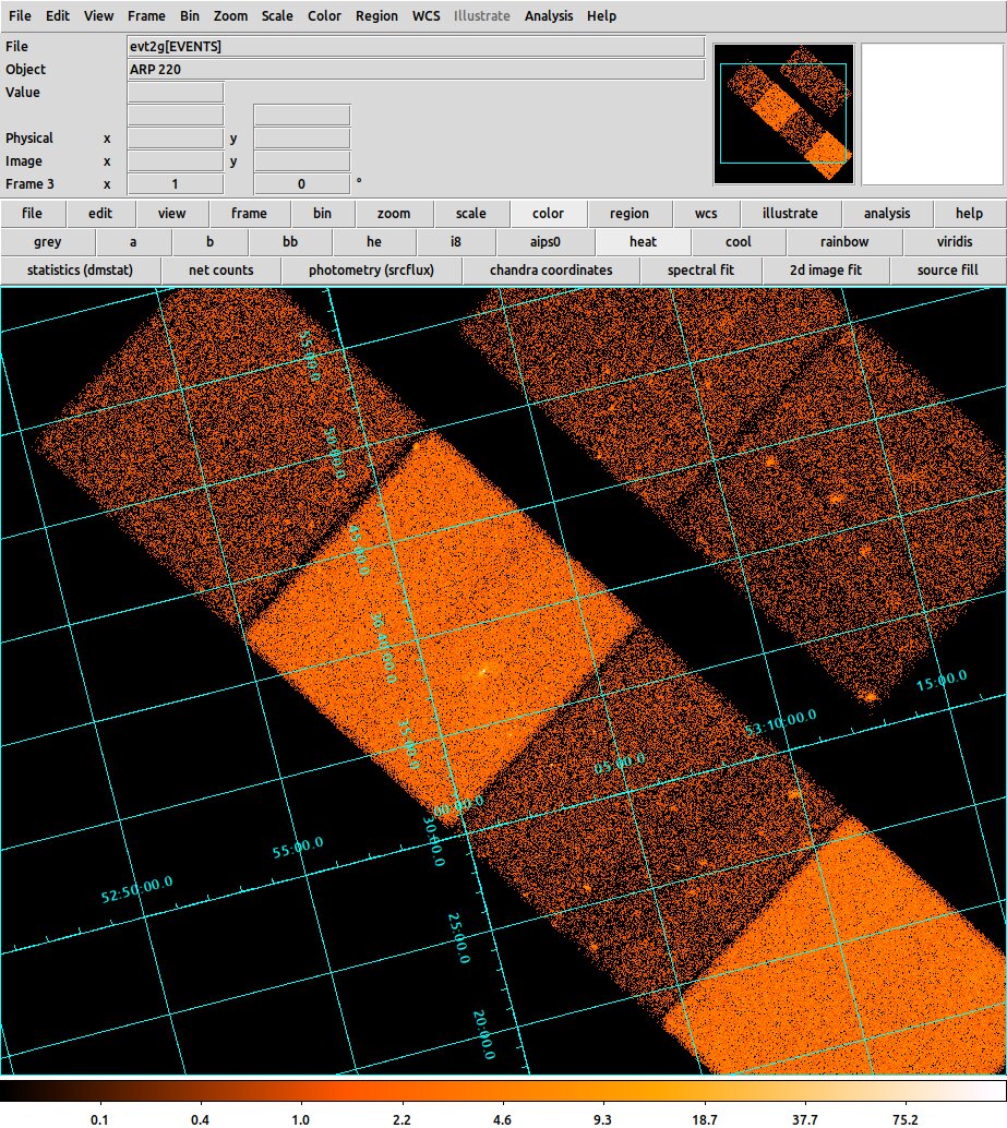
Coordinate grid example
| Command: | grid open |
| Menu: | Analysis - Coordinate Grid Parameters |
| Description: | Opens a dialog which controls the parameters of the coordinate grid. |
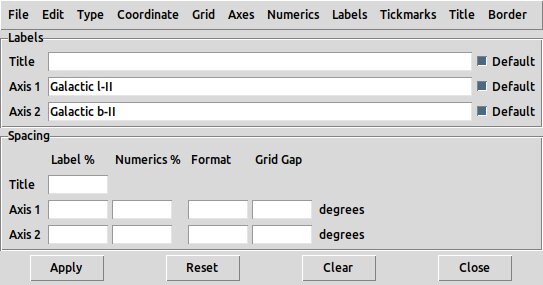
Coordinate grid parameters dialog
| Command: | grid close |
| Menu: | Analysis - Coordinate Grid Parameters - Close |
| Description: | Close the coord grid parameters dialog |
| Command: | grid grid yes|no |
| Menu: | Analysis - Coordinate Grid Parameters - Grid - Show |
| Description: | Deselecting this suppresses the grid but not the axes. |
| Command: | - |
| Menu: | Analysis - Coordinate Grid Parameters - Apply |
| Description: | Apply changes to the coordinate grid parameters to regenerate the coordinate grid. |
| Command: | grid reset |
| Menu: | Analysis - Coordinate Grid Parameters - Clear |
| Description: | Reset the coordinate grid parameters |
| Command: | grid grid color [value] |
| Menu: | Analysis - Coordinate Grid Parameters - Grid - Color |
| Description: | selects the color used for the grid lines and numerics. |
| Command: | grid grid width [value] |
| Menu: | Analysis - Coordinate Grid Parameters - Grid - Line |
| Description: | selects the lineweight used for the grid lines. |
| Command: | grid grid dash yes|no |
| Menu: | Analysis - Coordinate Grid Parameters - Grid - Line - Dash |
| Description: | selects dashed instead of continuous lines. |
| Command: | grid axes yes|no |
| Menu: | Analysis - Coordinate Grid Parameters - Axes - Show |
| Description: | controls whether the axis lines themselves are drawn. |
| Command: | grid axes color [value] |
| Menu: | Analysis - Coordinate Grid Parameters - Axes - Color |
| Description: | sets the color of the axis lines. |
| Command: | grid axes width [value] |
| Menu: | Analysis - Coordinate Grid Parameters - Axes - Line |
| Description: | sets the lineweight of the axis lines. |
| Command: | grid axes dash yes|no |
| Menu: | Analysis - Coordinate Grid Parameters - Axes - Line - Dash |
| Description: | sets the axes to be dashed lines or not |
| Command: | grid axes origin [option] |
| Menu: | Analysis - Coordinate Grid Parameters - Axes - Origin |
| Description: | This is greyed out by default except for 3D data.Specifies the origin as lower or upper on the three axes.Options are lll, llu, lul, luu, ull,m ulu, uul, uuu |
| Command: | grid title yes|no |
| Menu: | Analysis - Coordinate Grid Parameters - Title - Show |
| Description: | to suppress showing the grid title. |
| Command: | grid title text [value] |
| Menu: | Analysis - Coordinate Grid Parameters - Labels - Title |
| Description: | controls the title; unselect Defaultand enter a value to override |
| Command: | grid title def yes|no |
| Menu: | Analysis - Coordinate Grid Parameters - Labels - Title |
| Description: | Controls whether the default title is used |
| Command: | grid title font [value] |
| Menu: | Analysis - Coordinate Grid Parameters - Labels - Title - Font |
| Description: | Controls grid title font |
| Command: | grid title fontsize|fontweight|fontslant [value] |
| Menu: | Analysis - Coordinate Grid Parameters - Labels - Title - Font |
| Description: | Controls grid title font size, weight and slant |
| Command: | grid title color |
| Menu: | Analysis - Coordinate Grid Parameters - Title - Color |
| Description: | control grid title color |
| Command: | grid labels yes|no |
| Menu: | - |
| Description: | Show or supress grid axis labels |
| Command: | grid labels def1|def2 yes|no |
| Menu: | - |
| Description: | Use defaults for axis1 and axis2 labels |
| Command: | grid labels text1|text2 [value] |
| Menu: | Analysis - Coordinate Grid Parameters - Labels - Axis 1/Axis 2 |
| Description: | overrides the axis label names, if Default is unselected. |
| Command: | grid type analysis|publication |
| Menu: | Analysis - Coordinate Grid Parameters - Type - Analysis/Publication |
| Description: | Chooses between two styles. For Analysis,the grid extends beyond the active data area and for Publication it is truncated there. |
| Command: | grid axes type interior|exterior |
| Menu: | Analysis - Coordinate Grid Parameters - Type - Interior Axes/Exterior Axes |
| Description: | controls whether the axes are placed in the interior orat the edge of the image. |
| Command: | grid numerics yes|no |
| Menu: | Analysis - Coordinate Grid Parameters - Numerics - Show |
| Description: | shows or suppresses the axis numeric labels. |
| Command: | grid numerics type interior|exterior |
| Menu: | Analysis - Coordinate Grid Parameters - Type - Interior Numerics/Exterior Numerics |
| Description: | In publication mode only (see 'grid type'), controls whether the axis numeric labels are placed in the interior orat the edge of the image. |
| Command: | grid numerics vertical|horizontal |
| Menu: | Analysis - Coordinate Grid Parameters - Type - Vertical Text |
| Description: | If this is selected, the y axis numbers are printed in a vertical orientationinstead of parallel to the Y axis. |
| Command: | grid numerics font times|helvetica|courier |
| Menu: | Analysis - Coordinate Grid Parameters - Numerics - Font |
| Description: | Controls font for axis numerics |
| Command: | grid numerics fontslant/fontsize/fontweight [value] |
| Menu: | Analysis - Coordinate Grid Parameters - Numerics - Font |
| Description: | Controls font properties for axis numerics |
| Command: | grid numerics color [value] |
| Menu: | Analysis - Coordinate Grid Parameters - Numerics - Color |
| Description: | controls the color of the numeric labels. |
| Command: | grid border yes|no |
| Menu: | Analysis - Coordinate Grid Parameters - Border - Show |
| Description: | draws a border around the coordinate grid. |
| Command: | grid border color [value] |
| Menu: | Analysis - Coordinate Grid Parameters - Border - Color |
| Description: | controls the color of the border. |
| Command: | grid border width [value] |
| Menu: | Analysis - Coordinate Grid Parameters - Border - Line |
| Description: | controls the width of the border. |
| Command: | grid border dash yes|no |
| Menu: | Analysis - Coordinate Grid Parameters - Border - Line - Dash |
| Description: | controls dashed or solid lines for the border. |
| Command: | grid tickmarks yes|no |
| Menu: | Analysis - Coordinate Grid Parameters - Tickmarks - Show |
| Description: | shows or suppresses the axis tickmarks. |
| Command: | grid tickmarks color [value] |
| Menu: | Analysis - Coordinate Grid Parameters - Tickmarks - Color |
| Description: | controls the color of the tickmarks. |
| Command: | grid tickmarks width [value] |
| Menu: | Analysis - Coordinate Grid Parameters - Tickmarks - Line |
| Description: | controls the width of the tickmarks. |
| Command: | grid tickmarks dash yes|no |
| Menu: | Analysis - Coordinate Grid Parameters - Tickmarks - Line - Dash |
| Description: | controls dashed or solid lines for the tickmarks. |
| Command: | grid system [coordsys] |
| Menu: | Analysis - Coordinate Grid Parameters - Coordinate - WCS |
| Description: | The coordinates plotted are by default the primary WCS coordinates of the file (usually RA, Dec ICRS).However this can be altered by changing the selection with coordsys = WCS, Image, Physical, Amplifier, Detector. |
| Command: | grid sky [coordsys] |
| Menu: | Analysis - Coordinate Grid Parameters - Coordinate - Galactic/FK4/FK5/ICRS/Ecliptic |
| Description: | Select coordinate system for grid |
| Command: | grid skyformat degrees|sexagesimal |
| Menu: | Analysis - Coordinate Grid Parameters - Coordinate - Degrees/Sexagesimal |
| Description: | Set the format style of the coordinates printed |
| Command: | grid grid gap1|gap2|gap3 |
| Menu: | Analysis - Coordinate Grid Parameters - Spacing - Grid Gap - Axis 1/Axis 2 |
| Description: | Set the spacing of the grid lines on a given axis. |
| Command: | grid numerics gap1|gap2|gap3 |
| Menu: | Analysis - Coordinate Grid Parameters - Spacing - Numerics - Axis 1/Axis 2 |
| Description: | Set the spacing of the numerics relative to the axis lines on a given axis. |
| Command: | grid format1|format2 |
| Menu: | Analysis - Coordinate Grid Parameters - Spacing - Format - Axis 1/Axis 2 |
| Description: | Set format of numerics on grid.The format can be a standard C printf format with an extra leading percent, e.g. "%%1.7G", or it can be a special DS9 format as defined below. |
The format string is a sequence of case-insensitive characters from the list below. If options conflict, the rightmost character takes precedence except that d and h override t. The default formats are 'd.3', 'd.3' for degrees and 'hms.1', 'dms.1' for sexagesimal.
| Format character | Meaning |
| + | Indicates that a plus sign should be prefixed to positive values. By default, no plus sign is used. |
| z | Indicates that leading zeros should be prefixed to the value so that the first field is of constant width, as would be required in a fixed-width table (leading zeros are always prefixed to any fields that follow). By default, no leading zeros are added. |
| i | Use the standard ISO field separator (a colon) between fields. This is the default behaviour. |
| b | Use a blank to separate fields. |
| l | Use a letter ("h"/"d", "m" or "s" as appropriate) to separate fields. |
| g | Use a letter and symbols to separate fields ("h"/"d", "m" or "s", etc, as appropriate), but include escape sequences in the formatted value so that the Plot class will draw the separators as small super-scripts. |
| d | Include a degrees field. Expressing the angle purely in degrees is also the default if none of "h", "m", "s" or "t" are given. |
| h | Express the angle as a time and include an hours field (where 24 hours correspond to 360 degrees). Expressing the angle purely in hours is also the default if "t" is given without either "m" or "s". |
| m | Include a minutes field. By default this is not included. |
| s | Include a seconds field. By default this is not included. This request is ignored if "d" or "h" is given, unless a minutes field is also included. |
| t | Express the angle as a time (where 24 hours correspond to 360 degrees). This option is ignored if either "d" or "h" is given and is intended for use where the value is to be expressed purely in minutes and/or seconds of time (with no hours field). If "t" is given without "d", "h", "m" or "s" being present, then it is equivalent to "h". |
| . | Indicates that decimal places are to be given for the final field in the formatted string (whichever field this is). The "." should be followed immediately by an unsigned integer which gives the number of decimal places required, or by an asterisk. If an asterisk is supplied, a default number of decimal places is used which is based on the value of the Digits attribute. |
| Command: | grid labels gap1|gap2 |
| Menu: | Analysis - Coordinate Grid Parameters - Spacing - Label|Title \% - Axis 1/Axis 2 |
| Description: | Control of the spacing of the axis labels and title |