Regions
Regions are geometric shapes that can be defined interactively in DS9, or read in from a DS9 ascii region file or from a CIAO FITS region file.
The most common DS9 region is a circle (other region types are described below). It can be created interactively when the DS9 edit mode is Edit - Region, or can be specified in a region file which is loaded from the region menu.
Many regions can be defined in a single frame. A subset of them can be 'selected' (by clicking on them) and certain actions apply to selected regions.
| Command: | - |
| Menu: | - |
| Description: | KEYBOARD SHORTCUT: Shift-Drag: define a rectangle, select all regions within that rectangle. |
DS9 Region files
DS9 region files are text files with a particular syntax. The simplest region file is just a single line containing a shape description, for example
circle(4096.5,4096.5,8.2)
When you save the region to a file from DS9 you get some additional metadata
# Region file format: DS9 version 4.1
global color=green dashlist=8 3 width=1 font="helvetica 10 normal roman"
 select=1 highlite=1 dash=0 fixed=0 edit=1 move=1 delete=1 include=1 source=1
physical
circle(4096.5,4096.5,8.2)
A region file can contain multiple regions
# Region file format: DS9 version 4.1
global color=green dashlist=8 3 width=1 font="helvetica 10 normal roman"
 select=1 highlite=1 dash=0 fixed=0 edit=1 move=1 delete=1 include=1 source=1
physical
circle(4096.5,4096.5,8.2)
box(1268,1151,100,200)
or
# Region file format: DS9 version 4.1
global color=green dashlist=8 3 width=1 font="helvetica 10 normal roman"
 select=1 highlite=1 dash=0 fixed=0 edit=1 move=1 delete=1 include=1 source=1
physical;circle(4096.5,4096.5,8.2);box(1268,1151,100,200)
or
# Region file format: DS9 version 4.1
global color=green dashlist=8 3 width=1 font="helvetica 10 normal roman"
 select=1 highlite=1 dash=0 fixed=0 edit=1 move=1 delete=1 include=1 source=1
physical
circle 4096.5 4096.5 8.2
box 1268 1151 100 200
The parentheses forms of the shape specifications are what DS9 will use when saving a region to a file; the forms without parentheses are supported for back compatibility. Semicolons are equivalent to a newline.
The first line of the file, beginning with a hash symbol, describes the version of the file format. This line is optional.
The second line, beginning with 'global', defines region properties that will apply to all regions in the file.
The third line defines the coordinate system in which the coordinate values in the region are expressed.
Fourth and subsequent lines specify the individual region shapes. Shape definitions are of the form
+shape(param,param,...param) # prop=value prop=value prop=valueso that each shape has a set of parameters, and a set of properties whose values may be set. Parameters are required; properties may be omitted to choose their default values. If no properties are specified the hash mark may be omitted.
The leading + has no effect and is usually omitted. A leading minus sign indicates the region is meant to be excluded rather than included. For example
# Region file format: DS9 version 4.1
global color=green dashlist=8 3 width=1 font="helvetica 10 normal roman"
 select=1 highlite=1 dash=0 fixed=0 edit=1 move=1 delete=1 include=1 source=1
physical
circle(4096.5,4096.5,8.2)
-box(4100,4100,10,10)
denotes a circle with the part that overlaps with the box excluded.
Some `display-only' shapes instead use the syntax
# shape(param,param,...param) prop=value prop=value prop=valuewith the hash mark before instead of after the shape section.
Lines with a leading hash mark # which are not recognized as valid display-only shapes are ignored and treated as comments.
Other supported region formats
| Command: | - |
| Menu: | Edit - Preferences - Region - Default Format |
| Description: | allows the default output region file formatto be 'ds9' (default, DS9/Funtools); 'XML', 'CIAO', or obsolete legacy formats 'SAOtng', 'SAOimage', 'IRAF Pros',or an unannotated 'X Y' format. |
DS9 can also read CIAO FITS region binary tables.
- CIAO region files
DS9 also supports Chandra CIAO region files on both input and output. These files are like the DS9 files but don't have the header lines. So,
circle(4096,4096,25.2)
is a valid CIAO region file. Instead of BOX, CIAO has ROTBOX and RECTANGLE shapes which DS9 translates into BOX shapes. CIAO does not support display-only shapes, PANDA, or ELLIPSE/BOX ANNULUS shapes.
- SAOimage and IRAF-PROS region format:
- SAOimage POINT is mapped to DS9 box, circle, point
- SAOimage ROTBOX is mapped to DS9 box
- Line, Vector, Projection, Segment, Text, Ruler, Compass, Ellipse Annulus, Box Annulus, Panda, EPanda, BPanda are not supported.
Example of a PROS region file:
/m51.fits
# Mon Jan 16 16:09:43 1989
# shape x, y, [x dimension, y dimension], [angle]
 BOX(135.67,213.00,18.00,10.67)
 BOX(504.00,538.00,16.96,106.53,290.714)
 CIRCLE(129.00,306.67,9.89)
-ELLIPSE(486.00,468.00,36.53,44.08,329.036)
-POINT(83.00,349.00)
 POLYGON(131.00,245.00,120.67,280.33,165.00,245.00,140.00,234.67)
 BOX(149.67,205.00,30.00,12.00) & !BOX(149.67,205.00,20.00,8.00)
- Funtools
The Funtools regions are similar to DS9 but do not support Line, Vector, Projection, Segment, Text, Ruler or Compass.
- XY format
This format consists of a number of coordinate pairs, one per line. The coordinate format for both input and output is specified via the Save Regions Parameters menu or XPA regions point. The first two coordinates are read, the rest of the line is ignored. The comment character '#' may be used at the beginning of line and the line is ignored. This format is very useful for reading in coordinates from other external analysis programs, such as IRAF.
Example: # this is a comment
physical # this overrides the specified coordinate system
300 300
400 400 # this is a comment
Region mode
| Command: | mode none |
| Menu: | Edit - None |
| Description: | Left mouse button has its default behaviour. |
| Command: | mode region |
| Menu: | Edit - Region |
| Description: | In this mode, which was the default in early versions of DS9,the left button allows the user to create and edit regions.Regions can be either 'selected' or 'unselected'; certain actions applyto currently selected regions only. |
Details of button actions in region mode:
- If no region is currently selected: click to start creating a region with reference point at that location; hold down and move,
releasing to define the size of the region.
The type of region is predefined in the Region/Shape menu; the default is a circle.
- Clicking inside an existing region selects the region; clicking and dragging allows you
to move it.
- If a region is selected, clicking in an empty area of the image deselects the region
(i.e. returns you to the 'no region currently selected' state.)
- Double-clicking on a selected existing region brings up a dialog box allowing you
to change the region parameters, including color, line width, etc.
- If one region is selected, left-clicking in a different region selects
the new region and deselects the first one. Shift-left-clicking in a
different region selects the new region and keeps the old one(s) selected too.
- Shift-left-clicking outside a set of regions, then dragging, specifies
a rectangle; at release, all regions within that rectangle are selected.
- Middle and right buttons behave the same as for 'none' mode.
- Note that the list of regions is ordered, and regions are superimposed on each other with the first region at the
top and the last region at the bottom; this can easily be seen by making several overlapping regions with different
colors and with fill=1.
- Each region has a bounding box and a center. The center of a region is the centroid of the corners of the bounding box.
(this also applies to composite regions - the center of a composite region is the centroid of the composite's bounding box).
Rotating a region is done around its center.
The Region menu also has entries controlling region selection:
| Command: | region select all |
| Menu: | Region - All |
| Description: | selects all the regions currently defined |
| Command: | region select none |
| Menu: | Region - None |
| Description: | deselects all regions |
| Command: | region select invert |
| Menu: | Region - Invert |
| Description: | deselects all currently selected regions and selects all currently unselected regions |
| Command: | region select front|back |
| Menu: | Region - Front, Back |
| Description: | Selects the first or the last region in the list. |
| Command: | region move front|back |
| Menu: | Region - Move To Front/Back |
| Description: | moves the selected region to the beginning or end of the list. |
Region coordinate systems
The allowed coordinate system names in a region file are
| Name | System | Default unit | Meaning |
| image | image | pix | Pixel coordinates of the current image |
| physical | physical | scaled pix | Original pixel coords of instrument, as defined by CRPIXnP/CDELTnP or the IRAF keywords LTM/LTV |
| icrs | ICRS | deg | ICRS celestial coords, using WCS keywords in image |
| fk4 | FK4,B1950 | deg | FK4/B1950 coords |
| fk5 | FK5/J2000 | deg | FK5/J2000 coords |
| galactic | IAU galactic | deg | l(II), b(II) in degrees |
| ecliptic | ICRS ecliptic | deg | Ecliptic lon and lat, degrees |
| wcs | WCS | Whatever coord system is specified by the file's primary WCS | |
| wcsa | WCSA | Whatever coord system is specified by the file's secondary 'A' WCS | |
| linear | LINEAR | Linear coord system specified by the file's primary WCS |
If no coordinate system is specified, `physical' or `WCS' is assumed depending on the formatting (decimal or sexagesimal) of the coordinate values.
Region coordinate value, length and angle formats
Coordinate value formats
Values in these coordinate systems can be expressed in a variety of ways.
| Syntax | Example | Interpretation |
| [num] | 5.8 | Coordinate value in pixels for IMAGE,PHYSICAL, else in degrees |
| [num]d | 243.3d | Degrees |
| [num]r | 1.745r | Radians |
| [num]p | 1024.3p | Pixels in PHYSICAL system |
| [num]i | 512.0i | Image pixel number |
| [num]:[num]:[num] | 14:07:28.8 | hr:min:s for long-like coords, deg:min:s for lat-like coords |
| [num]h[num]m[num]s 10h20m15.1s | hr:min:s | |
| [num]d[num]m[num]s -00d20m15.1s | deg:min:s | |
Coordinate length formats
Arguments like circle radius or box length can use the following formats:
| Syntax | Example | Interpretation |
| [num] | 5.8 | Coordinate value in pixels for IMAGE,PHYSICAL, else in degrees |
| [num]d | 243.3d | Degrees |
| [num]r | 1.745r | Radians |
| [num]p | 1024.3p | Pixels in PHYSICAL system |
| [num]i | 512.0i | Image pixel number |
| [num]" | 20.4" | Arcseconds |
| [num]' | 20.4' | Arcmin |
| Command: | - |
| Menu: | Edit - Preferences - Region - Default Length |
| Description: | The default length unit is set; it may be Degrees (default), ArcMin or ArcSec. |
Angle formats
Angles (e.g. for the orientation of an ellipse) are always expressed as a simple number, interpreted as degrees.
Region shapes
Here I define the region shape types, their parameters, and the properties that are specific to those shapes; I also discuss how to create them interactively. As noted earlier, region creation is done either by reading a region file, or by selecting Edit - Region and then left clicking at the location you want the region to be at.
| Command: | - |
| Menu: | Region - Color - Fill |
| Description: | If this flag is set, the newly created region is displayed as filled, otherwise as an outline. |
| Command: | - |
| Menu: | Region - Region Parameters - Auto Plot Statistics |
| GUI Default: | Edit - Preferences - Region - Auto Plot - Statistics |
| Description: | If this flag is set, upon region creation a popup window appears showingvarious statistics of the image pixels within the region. |
| Command: | - |
| Menu: | Region - Region Parameters - Auto Plot 2D |
| Description: | If this flag is set, upon region creation a popup window appears showinga line plot of the pixel values vs coordinate. |
| Command: | - |
| Menu: | Region - Region Parameters |
| Description: | This menu lets you control some display properties that newly created regionswill have. It does not affect previously created regions. |
| Command: | region epsilon [value] |
| Menu: | Edit - Preferences - Region - Mouse Click Epsilon |
| Description: | Interactive region creation look and feel can be modified by changing epsilonfrom the default value of 3 pixels to a value between 2 and 10 pixels. This `epsilon' determines how close to the region the pointer position must beto successfully select it by clicking.Example: xpaset -p ds9 region epsilon 5 |
Basic shapes
| Command: | region shape [value] |
| Menu: | Region - Shape |
| Description: | Select the shape to be created when you click in the image |
| Command: | region open |
| Menu: | Region - Get Information |
| Description: | Bring up the region shape dialog box. This can also be done by double clicking on a region. |
| Command: | region close |
| Menu: | Region - [shape] - Close |
| Description: | Close the region shape dialog box. |
| Command: | region selected |
| Menu: | - |
| Description: | Used with xpaget; `xpaget ds9 region selected' writes the region details to standard output. |
There are four region types that define areas on the image.
- For `circle',
- DS9 region file syntax and example:
circle(x,y,radius) # fill=[0|1]
circle(4096.5,4096.5,8.2) # fill=0
- Parameters: fill. Is the circle filled in; 0 = no (default), 1 = yes.
- Mouse creation: the reference
point is its center, and the release point defines the radius.
Command: - Menu: Edit - Preferences - Region|Illustrate - Circle - Radius Description: Sets the default circle radius (initially 20 pixels)
- DS9 region file syntax and example:
- For `box':
- DS9 region file syntax and example:
box(x,y,width,height,angle)# fill=[0|1]
box(4080.0,4090.0,20.0,10.0,0.0) # fill=0
The angle value is optional and defaults to zero. - Mouse creation: the reference point is one corner. Dragging increases the sides of the box,
which are parallel to the image axes. The angle can be changed from the region parameter
dialog which can be popped up by selecting the region (click inside it) and then
double-clicking again inside the selected region (or by using the Region - Get Information menu item).
Command: - Menu: Edit - Preferences - Region|Illustrate - Box - Size 1/Size 2 Description: The default side lengths of the box are 80 and 40 pixels, controlled by this command.
- DS9 region file syntax and example:
- `ellipse'
- DS9 region file syntax and example:
ellipse(x,y,a,b,angle) # fill=[0|1]
ellipse(4096.5,4096.5,48,24,45.0)
- Mouse creation: like circle; the ellipticity is controlled by dragging up/down vs left/right.
The ellipse axes are always parallel to the image axes.
Command: - Menu: Edit - Preferences - Region|Illustrate - Ellipse - Radius 1/Radius 2 Description: Controls default size of ellipse.
- DS9 region file syntax and example:
- For `polygon'
- DS9 region file syntax:
polygon(x1,y1,x2,y2,x3,y3 ...) # fill=[0|1]
- Mouse creation: clicking and dragging creates a square centered on the click location
with size determined by the drag release point. After release, clicking again inside the square
selects it. Once selected, clicking again on the boundary of the square creates an additional point
(node) that may be dragged; subsequent clicks will add more points to the polygon. Note that
clicking on the boundary *before* selecting the region will just create an additional polgyon region,
probably not what you wanted.
Command: - Menu: Edit - Preferences - Region|Illustrate - Polygon - Width/Height Description: Controls default size of initial square, initially 20 x 20
- DS9 region file syntax:
Vector shapes
Four additional shapes allow a set (vector) of regions to be defined.
- `annulus':
- DS9 region file syntax and example:
annulus(x,y,r1,r2)
annulus(4388,4226,15,30)
annulus(x,y,r1,r2,r3,...)
annulus(4388,4226,15,30,45,62,90)
Additional radii may be defined for a set of concentric annuli, as in the second example. This capability is also present for the elliptical annulus and box annulus shapes described below.
- Mouse creation: click draws an annulus, with a fixed ratio of inner and outer circle, the outer radius
determined by dragging before releasing. Once released and then click-selected, clicking on
the individual circles allows you to change their radii individually. Selecting the annulus region by clicking
and then performing 'control - drag', you can create additional annuli. Also,
in the double-click dialog box, you can change the number of annuli by typing in the number
to the 'Annuli' entry, then click Generate, then Apply.
Command: - Menu: Edit - Preferences - Annulus - Annulus - Radius - Inner/Outer Description: Controls default radii of annulus, initally 15 and 30 pixels Command: - Menu: Edit - Preferences - Annulus - Annulus - Annuli Description: sets the default number of annuli at creation. Command: region analysis radial open Menu: Annulus - Analysis - Radial Profile Description: Opens a plot window showing surface brightness vs radius. Useful for multiple annuli.
- DS9 region file syntax and example:
- `elliptical annulus':
- DS9 region file syntax and example:
ellipse(x,y,a,b,r1,r2,angle)
ellipse(4124,4132,18.5,63.5,37,127,0)
- Mouse creation: Similar to annulus. The double-click dialog box
allows the annulus orientation to be selected, and the ellipticity (change the major or
minor axis, then click Generate, then Apply).
Command: - Menu: Edit - Preferences - Annulus - Elliptical Annulus - Inner - Major/Minor Description: Sets defaul elliptical inner annulus shape (defaults 40, 20) Command: - Menu: Edit - Preferences - Annulus - Elliptical Annulus - Outer - Major Description: Sets default outer annulus major axis (default 60) Command: - Menu: Edit - Preferences - Annulus - Elliptical Annulus - Annuli Description: Sets default number of annuli, default 1
- DS9 region file syntax and example:
- `box annulus':
- DS9 region file syntax and example:
box(x,y,width1,height1,width2,height2,angle)
box(4348.501,4214.499,60.499,46.501,120.998,93.002,0)
- Mouse creation: Similar to elliptical annulus, but the regions drawn are boxes.
Command: - Menu: Edit - Preferences - Annulus - Box Annulus - Inner - Width/Height Description: Set Box annulus inner size (defaults 80, 40) Command: - Menu: Edit - Preferences - Annulus - Box Annulus - Outer - Width Description: Set Box annulus outer size (default 120) Command: - Menu: Edit - Preferences - Annulus - Box Annulus - Annuli Description: Set Box annulus default number of annuli (default 1))
- DS9 region file syntax and example:
- `panda'
The panda region defines a set of annuli with sectors.
- DS9 region file syntax and example:
panda(x,y,theta1,theta2,ntheta,r1,r2,nr)
panda(4213,4295,0,360,4,67,135,1)
panda(4212.9,4295.8,0,270,4,67.8,135.6,2)
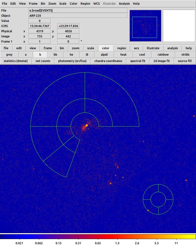
Example of panda regions
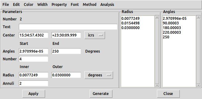
Panda shape dialog
- Mouse creation: draws an annulus in which the region between the inner and outer circles
is divided in NE, NW, SE, SW sectors. The number of sectors and annuli, and the
angular range (default 0 to 360 deg) can be changed in the double-click
dialog box: change the values then click Generate, then Apply.
The default parameters are controlled by
Command: - Menu: Edit - Preferences - Panda - Panda - Radius - Inner/Outer Description: (defaults 15, 30) Command: - Menu: Edit - Preferences - Panda - Panda - Angles - Start/Stop Description: (default 0, 360 deg) Command: - Menu: Edit - Preferences - Panda - Panda - Angles - Number Description: (default 4) Command: - Menu: Edit - Preferences - Panda - Panda - Annuli Description: (default 1) Command: region analysis panda open Menu: Panda - Analysis - Radial Profile Description: Opens a plot window showing surface brightness vs radius, one line per sector. Useful for multiple annuli.
- DS9 region file syntax and example:
- `epanda' and 'bpanda'
are the elliptical and box versions of the panda region, with separately specified
inner and outer minor and major axis radii and an optional rotation angle phi.
- DS9 region file syntax and example:
epanda(x,y,theta1,theta2,ntheta,a1,b1,a2,b2,nr,phi)
bpanda(x,y,theta1,theta2,ntheta,a1,b1,a2,b2,nr,phi)
The ratio a2/b2 must be the same as a1/b1.
- Mouse creation: as for panda, but while creating, dragging vertically and horizontally alters the ellipticity.
The default parameters are controlled by
Command: - Menu: Edit - Preferences - Panda - Elliptical Panda/Box Panda - Radius - Inner/Outer Description: (defaults 15, 30) Command: - Menu: Edit - Preferences - Panda - Elliptical Panda/Box Panda - Angles - Start/Stop Description: (default 0, 360 deg) Command: - Menu: Edit - Preferences - Panda - Elliptical Panda/Box Panda - Angles - Number Description: (default 4) Command: - Menu: Edit - Preferences - Panda - Elliptical Panda/Box Panda - Annuli Description: (default 1)
- DS9 region file syntax and example:
Display-only shapes
Other region types are purely for illustrations and analysis. They define a line or curve on the image which can be used to generate a 2D plot, or for 3D data a 3D plot. The Region Parameters - Auto Plot 2D/Auto Plot 3D menu options, or alternatively Edit - Preferences - Region - Auto Plot - 2d/3d, determine whether or not the plot is shown.
- 'point' draws a single point symbol and has a number of subtypes (circle, box, diamond, etc).
Parameters describe the symbol type, the size of the symbol, and its color. The symbol type is required.
- DS9 region file syntax and example:
point(x,y) # point=subtype
point(3883,4387) # point=diamond
point(x,y) # point=subtype size color=value
point(3883,4387) # point=diamond 40 color=cyan
- Mouse creation: Clicking creates the point;
click-dragging does nothing. Additional clicks create new points.
Command: - Menu: Edit - Preferences - Region - Point - Size Description: The default size of the point at creation is set with this, initially 11 pixels
- DS9 region file syntax and example:
- `line' draws a line.
Parameters L and R can be 0 or 1; if 1, an arrowhead is drawn on the left (L) or right (R) end of the line.
The 'line' region can be used to make a scale bar on a plot for publication. Double-clicking to get the region-dialog allows you to read off the current length in angular units. If you click-drag one end of the line you can adjust its length, and the displayed value will update, allowing you to choose a suitable lengthy (say 1 arcmin). The region dialog also has a Text box where you can enter a label to be displayed next to the line.
- DS9 region file syntax and example:
line(x1,y1,x2,y2) # line=L R line(3881,4297,3913,4189) # line=0 0 line(3881,4297,3913,4189) # line=0 1 line(15:35:01.8309,+23:29:10.479,15:34:59.6494,+23:29:10.976) # line=0 0 text={30"} - Mouse creation: clicking defines one end of the line; dragging and releasing defines the other end. Once the line is defined, selecting it by clicking on it and then clicking again on one end allows you to drag that end and extend or move the line. Clicking on the middle of a selected line allows you to move it around.
- DS9 region file syntax and example:
- 'vector'
Vector draws a line with an arrow. However the optional parameter vector=0 can switch off the arrow, just as for 'line' the parameter line=0 1 can swich on an arrow. The real difference between 'line' and 'vector' is that the first specifies two endpoints, while the second specifies one endpoint and a length/angle.
- DS9 region file syntax and example:
# vector(x,y,length,angle) vector=1
# vector(4099,4012,125.64235,33.310631) vector=1
Note the leading # in the syntax here. - Mouse creation: vector is like 'line', but an arrowhead is drawn at the release end of the line.
- DS9 region file syntax and example:
- `projection'
- DS9 region file syntax and example:
# projection(x1,y2,x2,y2,0)
# projection(3811,3981,3932,4027,0)
# projection(x1,y2,x2,y2,width)
# projection(3904.9992,4213.0005,4289.0002,4255.0008,146.34146)
Note the leading # in the syntax here. In the second case with finite width, the xy values define the lower boundary of a box and the width is in the upward (physical +y) direction to define the width of the box. - Mouse creation: draws a line, and pops up a line graph showing the intensity profile of
image pixels values along that line.
By double-click selection you can use the dialog box to set width, as in the second
example above.
Command: - Menu: Edit - Preferences - Region - Projection - Thickness Description: Controls default thickness of the width, initially 0
- DS9 region file syntax and example:
- `segment': Segment is an open polygon, a series of line segements.
- DS9 region file syntax and example:
# segment(x1,y1,x2,y2,x3,y3,...)
# segment(3682.9316,4477.0684,3803,4185,3917,4265,3895,4321,4003,4327)
- Mouse creation: `segment' is like an open polygon. Initially it makes a diagonal line. Click to select and then click again in the line to add a break point. Now you have a broken line with a node in the middle. Clicking on the node allows you to move that node around; clicking elsewhere in the line adds a new node.
- DS9 region file syntax and example:
- `text' - allow user to annotate the image with text
- DS9 region file syntax and example:
# text(x,y) text={blah blah} # text(3991,4381) text={Region} # text(x,y) textangle=theta color=name width=w font="font desc" text={blah blah} # text(3990,4380) textangle=19 color=red width=2 font="times 14 normal roman" text={All the data} - Mouse creation: clicking adds the word 'Region' to the image. Double-clicking brings up a control box allowing you to change the text and properties such as the font and color.
- DS9 region file syntax and example:
- `ruler'
'ruler' draws a two-sided arrow and text showing the length of the arrow. If the angle is nonzero, dashed lines projecting the arrow in x and y directions are also shown. The optional 'format' parameter lets you specify a C printf style format to control the way the number will be displayed.
The 'ruler' region is mainly used for interactive measurements; for a distance indicator on printed output the 'line' region is recommended.
- DS9 region file syntax and examples:
# ruler(x1,y2,x1,y2) ruler=coordsys unit # ruler(x1,y2,x1,y2) ruler=coordsys unit format={c-format} # ruler(4161,4177,4309,4337) ruler=fk5 degrees # ruler(4161,4177,4309,4337) ruler=fk5 physical # ruler(4116.0002,4071.0003,4297,4174) ruler=fk5 degrees format={%8.3f} - Mouse creation: draws a two-sided arrow and text showing the length of the arrow in world coordinate units (degrees). The double-click dialog box allows you some control over what quantity (physical or world) is measured and in what units.
- DS9 region file syntax and examples:
- `compass'
This draws a pair of arrows, one north and one east, to indicate the cardinal directions on the image. Changing the wcs to galactic makes the arrows be in the direction of galactic north and east. The labels used for the arrows can be edited. The NA and EA parameters can be 1 or 0 to control whether or not the north and east axis lines terminate in an arrowhead.
- DS9 region file syntax and example:
# compass(x,y,length) compass=wcs {North-label} {East-label} NA EA # compass(4091,4239,86.838931) compass=fk5 {N} {E} 1 1 # compass(36.6126736,53.0266578,65.355") compass=galactic {b} {l} 1 1 # compass(4091,4239,86.838931) compass=fk5 {Severniy} {Vostochniy} 1 1 - Mouse creation: draws a northward and eastward arrow (dragging selects the lengths of the arrows), labelled 'N' and 'E', useful for showing the axis directions on an illustration. The double-click dialog box allows you to change the labels.
- DS9 region file syntax and example:
| Command: | region analysis plot2d open |
| Menu: | [shap] - Analysis - Plot2D |
| Description: | If a currently selected region is a display-only region, this will pop up aplot with the pixel values vs distance along the region |
Composite regions
One may also define a `composite region' by selecting multiple regions (e.g. using the shift-click to select second and subsequent regions) and then the Region/ Composite Region / Create menu entry. The composite region can then be moved around as a unit. It can be saved to a DS9 region file; an example is:
# Region file format: DS9 version 4.1
global color=green dashlist=8 3 width=1 font="helvetica 10 normal roman" select=
1 highlite=1 dash=0 fixed=0 edit=1 move=1 delete=1 include=1 source=1
physical
# composite(3988.5,4200,0) || composite=1
circle(4105,4153,46.6119) ||
circle(3872,4247,20)
circle(4253,4207,20)
Here the '# composite(x,y,angle)" directive and the || after the first circle region specify that the first two circle entries form a composite region; the third circle in this example is an independent region not part of the composite.
| Region File syntax: | composite |
| # composite (3988.5,4200.0) || composite=1 | |
| Command: | region composite |
| Menu: | Region- Composite Region - Create |
| Description: | Creates a composite region. |
| Command: | region dissolve |
| Menu: | Region - Composite Region - Dissolve |
| Description: | Dissolve a composite region |
Template (Footprint) regions
In the GUI region menu, the Region - Instrument FOV entry allows the user to specify one of a set of template regions defined relative to the WCS pointing direction. Supported examples include the Chandra ACIS instrument footprint.
These regions are defined in terms of component regions (polygons, boxes etc). Saving such a region to a file saves the template as a composite region made up of these component regions.
Users may define their own templates and load them via the Region - Template menu.
| Command: | region template [filename] |
| Menu: | Region - Template |
| Description: | Open a template region file. |
| Command: | region template [filename] at [x y coordsys] |
| Menu: | Region - Template |
| Description: | Open a template region and relocate it. Example:region template foo.tpl at 13:29:55.92 +47:12:48.02 fk5 |
| Command: | region savetemplate [filename] |
| Menu: | Region - Template |
| Description: | Save a template region to a file. |
Generic region properties
These properties may be associated with a region in the properties section of a region file entry; most of the following properties may also be specified in the 'global' line of a region file, and they may be set in the interactive GUI in the Region menu (submenus Color, Properties, Font, etc).
First some properties that change the display of the region:
| Region File syntax: | color |
| # color=green# color=#48f | |
| Command: | region color [value] |
| Menu: | Region - Color |
| Description: | Changes the region color. Values may be color names or hex values with 3, 6 or 9 digits.The default region color is green. |
| Region File syntax: | fill |
| # fill = 1 | |
| Command: | region fill yes|no |
| Menu: | Region - Fill |
| Description: | Determines if the region is displayed as an outline shape (fill=0) or a shapefilled with the current region color (fill=1). In the GUI the fill value may be checked (1) orunchecked (0) in the Region - Color menu. |
| Region File syntax: | width |
| # width=2 | |
| Command: | region width [value] |
| Menu: | Region - Width |
| Description: | Determines the width of the line used to render the region outline. Default 1, valuesallowed are 1 to 4. |
| Region File syntax: | dash |
| # dash=1 | |
| Command: | region dash yes|no |
| Menu: | Region - Width - Dash |
| Description: | Lines will be dashed, using the current dashlist value. (Default 0). |
| Region File syntax: | dashlist |
| #dashlist=a b#dashlist=4 2 | |
| Command: | - |
| Menu: | - |
| Description: | Dashlist. Sets the dash sequence to use if the dash property is set.The first parameter is the length of the dash, the second is the length of the inter-dash gap.Can only be set in the region file itself. |
| Region File syntax: | text |
| # text={This message has both a " and ' in it} | |
| Command: | - |
| Menu: | - |
| Description: | Text. Draws the given text next to the region as a label. |
| Region File syntax: | font |
| # font="times 12 bold italic" | |
| Command: | region font [value] |
| Menu: | Region - Font |
| Description: | Determines the font family of any text used. Example: region font times.The default is 'helvetica 10 normal roman'. Options are times, helvetica, courier. |
| Region File syntax: | font |
| # font="times 12 bold italic" | |
| Command: | region fontsize [value] |
| Menu: | Region - Font - Size |
| Description: | Determines the font size of any text used. Example: xpaset -p ds9 region fontsize 12.Predefined menu options are 9, 10, 12, 14, 16, 20, 20, 30, 36, 72; there isan option for `other font size' where a numerical integer value can be entered. |
| Region File syntax: | font |
| # font="times 12 bold italic" | |
| Command: | region fontweight [value] |
| Menu: | Region - Font - Weight |
| Description: | Determines the font weight for any text used. Example: xpaset -p ds9 region fontweight boldOptions are: normal, bold. |
| Region File syntax: | font |
| # font="times 12 bold italic" | |
| Command: | region fontslant [value] |
| Menu: | Region - Font - Slant |
| Description: | Determines the font slant for any text used. Example: xpaset -p ds9 region fontslant italic.Options are: roman, italic |
| Region File syntax: | source|background |
| # source# background | |
| Command: | region source|background |
| Menu: | Region - Properties - Source/Background |
| Description: | Properties that associate a region as being either source or background,or have more specific 'tags' associated.These are not used by DS9 directly, but other applications may use them and thexpaget command can test them: 'xpaget ds9 region background' tests if the currentlyselected region is a background one.KEYBOARD SHORTCUT: s (set source property); b (set background property for selected region). |
| Region File syntax: | include |
| global include = 0 | |
| Command: | region include|exclude |
| Menu: | Region - Properties - Include/Exclude |
| Description: | This may only be used in the 'global' line; include=1 or include=0 areset in the individual region lines using the leading + or -. Default is include=1.KEYBOARD SHORTCUT: i (set include =1); e (set include = 0). |
Another set of properties control the interactive behaviour:
| Region File syntax: | fixed |
| # fixed = 1 | |
| Command: | region fixed yes|no |
| Menu: | Region - Properties - Fixed In Size |
| Description: | fixed: if this is set to 1, changes to the image magnification do not scale the region sizeaccordingly. Default is 0. |
| Region File syntax: | select |
| # select = 0 | |
| Command: | - |
| Menu: | - |
| Description: | select: if this is set to 0, mouse actions can neither select, edit, nor move the region.Default is 1. |
| Region File syntax: | highlite |
| # highlite = 0 | |
| Command: | - |
| Menu: | - |
| Description: | highlite: if this is set to 0, selecting the region does not make the `edit handles' visible.Default is 1. |
| Region File syntax: | edit |
| # edit = 0 | |
| Command: | region edit yes|no |
| Menu: | Region - Properties - Can Edit |
| Description: | edit: if this is set to 0, mouse actions do not allow the region to be edited even when selected.Default is 1. |
| Region File syntax: | delete |
| # delete = 0 | |
| Command: | region delete yes|no |
| Menu: | Region - Properties - Can Delete |
| Description: | delete: if this is set to 0, mouse actions do not allow the region to be deleted.Default is 1. |
| Region File syntax: | move |
| # move = 0 | |
| Command: | - |
| Menu: | Region - Properties - Can Move |
| Description: | move: if this is set to 0, mouse actions do not allow the region to be moved even when selected.Default is 1. |
| Region File syntax: | rotate |
| # rotate = 0 | |
| Command: | region rotate yes|no |
| Menu: | Region - Properties - Can Rotate |
| Description: | rotate: if this is set to 0, mouse actions do not allow the region to be rotated even whenselected.Default is 1. |
Regions can be copied and pasted using xpaset:
| Command: | region copy|cut|paste |
| Menu: | - |
| Description: | Copy, cut or paste seleted region. The paste commandtakes the coordsys as the argument, e.g. xpaset -p ds9 region paste wcs |
Region tags
| Region File syntax: | tag |
| # tag ={Group 1}# tag={Quasars} tag={PointSrcs} | |
| Command: | region group [tag] new |
| Menu: | Region - New Group |
| Description: | A way to group relatedregions. A single region line may have multiple tags associated.To select multiple regions, shift-click on thesecond and subsequent regions, or click-drag to select all regions within a rectangle.KEYBOARD SHORTCUT: g (create a new group). Shift-g (create a new group with default name). |
| Command: | region group [tag] select |
| Menu: | - |
| Description: | Select all regions in a tag group |
| Command: | region group [tag] update |
| Menu: | - |
| Description: | Update a tag group. For example : select the group. Now deselect some regions or select additional ones. Then 'update' willupdate the group membership list. |
| Command: | region group [tag] color [value] |
| Menu: | - |
| Description: | Set color for regions in a tag group |
| Command: | region group [tag] font [string] |
| Menu: | - |
| Description: | Set font for regions in a tag group. Example: region group foo font {times 14 bold} |
| Command: | region group [tag] cut|copy|delete |
| Menu: | - |
| Description: | Copy, cut, delete regions in a tag group |
| Command: | region group [tag] move [dx] [dy] |
| Menu: | - |
| Description: | Adjust position of all regions in a tag group |
| Command: | region group [tag] movefront|moveback |
| Menu: | - |
| Description: | Move all regions in a group to the front or back |
| Command: | region group [tag] property [name] yes|no |
| Menu: | - |
| Description: | Set the named property for all regions in a group. Example: region group foo property fill yes |
| Command: | region groups |
| Menu: | Region - Groups |
| Description: | Brings up a dialog which lists the named groups. Clicking on the name of a group selects all the regionsin that group. The same region can belong to more than one group. |
Special region directives for complicated data
- Tile: For a mosaic detector with multiple segments (tiles), some coordinate
systems (image, physical) apply on a per-tile basis. We can specify we are referring to tile 2 by
tile 2;point(100,100)
- Multiple WCS; FITS supports alternate WCS to the primary one, distinguished by a trailing letter
(e.g. CTYPE2B keyword for WCS B). The primary WCS uses no trailing letter. We can specifiy this a wcsx keyword:
wcsa;point(100,100)
wcsf;point(50,50)
wcs;point(1,10)
Region I/O
| Command: | region load [filename] |
| Menu: | Region - Open |
| Description: | This menu item puts up a file manager dialog to allow loading of region files from disk.By default only files with names ending in '.reg' are displayed in the dialog; you can click'All' for all files to be displayed. The filename to be loaded is shown in a selection text box,and you can edit this name.On selecting a filename with 'ok', a new dialog pops up allow you to controlthe file format to be read and whether it goes in the current frame or all frames. Youcan also override the region colors here. Usually you'll just want to click OK again. |
| Command: | region save [filename] |
| Menu: | - |
| Description: | Allows you to save all currently defined regions to a file.The first dialog is similar to that from Region - Open and allows you to edit the filename.It will warn you if you are overwriting an existing file. The second dialog allows you to selectthe output format and coordinate system. |
| Command: | region format ds9|xml|ciao|saotng|saoimage|pros|xy |
| Menu: | Region - Save - Save Regions - Format |
| Description: | Specify region file format flavour to save the regions in |
| Command: | region system image|physical|wcs|wcsa-z |
| Menu: | Region - Save - Save Regions - Coordinate System |
| Description: | Specify coordinates for output region file |
| Command: | region sky fk4|fk5|icrs|galactic|ecliptic |
| Menu: | Region - Save - Save Regions - Coordinate System |
| Description: | Specify celestial coordinates for output region file |
| Command: | region skyformat degrees|sexagesimal |
| Menu: | Region - Save - Save Regions - Coordinate System |
| Description: | Specify celestial coordinate representation for output region file |
| Command: | region save select [filename] |
| Menu: | Region - Save Selection |
| Description: | This is like Region - Save but only writes out the currently selectedregions. |
| Command: | region delete |
| Menu: | Region - Delete All |
| Description: | deletes all currently defined regions. |
| Command: | region delete select |
| Menu: | Region - Delete Selection |
| Description: | deletes all currently selected regions. KEYBOARD SHORCUT: Del |
| Command: | region delete load [filename] |
| Menu: | Region - Delete All and Open |
| Description: | is simply a combination of Region - Delete All followed byRegion - Open. |
| Command: | region command [string] |
| Menu: | - |
| Description: | Add a region. Example: 'region command {circle 100 100 20} |
Region information
| Command: | region strip yes|no |
| Menu: | - |
| Description: | Display only selected regions (yes) or all regions (no, default) |
| Command: | region show yes|no |
| Menu: | - |
| Description: | Regions are or are not visible on the display |
| Command: | region showtext yes|no |
| Menu: | - |
| Description: | Region text labels are or are not visible on the display |
| Command: | region list |
| Menu: | Region - List |
| Description: | lists all currently defined regions. It pops up the dialog to chooseformat and coordinate system to list the regions in. On pressing OK, it then raises a windowshowing what would be written to the region file if you did 'Region - Save'. |
| Command: | region list select |
| Menu: | Region - List Selection |
| Description: | is like Region - List but only lists the selected regions. |
| Command: | - |
| Menu: | Region - Get Information |
| Description: | pops up dialogs, one for each currently selected region,allowing access to the region edit properies (position, color, etc). This menu entry isreally 'Region - Allow Me To Edit It'. |
| Command: | region [-options] |
| Menu: | - |
| Description: | Access region information via xpaget.Options are of the form "-opt value" and include:-format ds9, ciao, saotng, saoimg, pros, xy-system image, physical, wcs, wcsa...z-sky fk4, fk5, icrs, galactic ecliptic-skyformat degrees, sexagesimal-delim nl-delim [character]-prop select, edit, move, rotate, delete, fixed, include, source 1, source 0-group [tag]-strip yes|no-wcs yes|noExample: xpaget ds9 region -format ds9 -system wcs -sky fk5 -skyformat sexagesimal -prop edit 1 -group foo |
| Command: | region centroid |
| Menu: | Region - Centroid |
| Description: | Calculates the centroid of the data near the middle of the selected region andadjusts the region to be centered at that point, redisplaying it.A circle of radius r (default 10) pixels is used around the region center, and n (default 30) iterations are done. |
| Command: | region centroid radius|iteration [value] |
| Menu: | Region - Region Parameters - Centroid Parameters - Radius/Iteration |
| GUI Default: | Edit - Preferences - Region - Centroid - Radius/Iteration |
| Description: | Control r or n parameter for centroiding |
| Command: | region centroid auto yes|no |
| Menu: | Region - Region Parameters - Auto Centroid |
| Description: | If set, a newly created region executes this procedureautomatically. |
| Command: | region analysis stats open|close |
| Menu: | Region - Get Information - Analysis - Statistics |
| Description: | open a dialog showing various statistics on the pixel values within the region. |
| Command: | region analysis stats save |
| Menu: | Region - Get Information - Analysis - Statistics - File - Save Data |
| Description: | write the stats info to a file |
| Command: | region analysis histogram open|close |
| Menu: | Region - Get Information - Analysis - Histogram |
| Description: | open a plot showing a histogram of the pixel values within the region. |
| Command: | region analysis histogram save |
| Menu: | Region - Get Information - Analysis - Histogram - File - Save Data |
| Description: | write the histogram to a file |
| Command: | region analysis plot3d open|close |
| Menu: | Region - Get Information - Analysis - Plot3D |
| Description: | For a data cube, open a plot showing a histogram of the pixel values within the regionas a function of the z slice number |
| Command: | region analysis plot3d open|close |
| Menu: | Region - Get Information - Analysis - Plot3D - File - Save Data |
| Description: | For a data cube, save a histogram of the pixel values within the regiona a function of slice number |